Kit Bash
Part Four in a Series
![]()
Kit Bash
Part Four in a Series
|
By:
Steve McGuire |

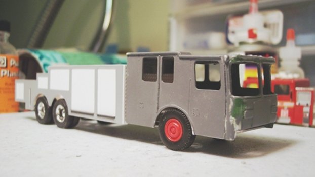
Smeal Brochure
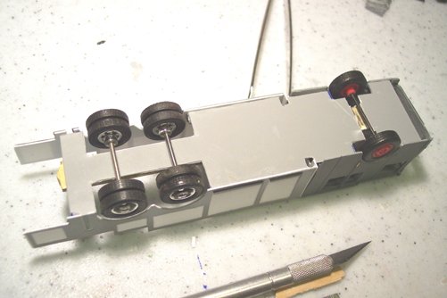
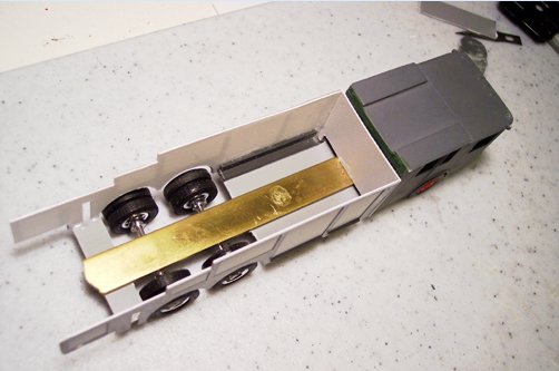
Test fit. The cab is not yet joined to the body, but it fits
the base perfectly and can stand by itself.
| I received feedback (always welcome) from one
reader who said that he enjoyed parts 1, 2, and 3 and was looking
forward to reading parts 4 through 2,000! Point taken and well
received. Instead of piece meal updates, the segments for this
feature will be longer, with more information and pictures. Another
reader pointed out that on the real truck, the jump body is slightly
wider than the cab. I was able to adjust for that, thanks to his
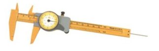
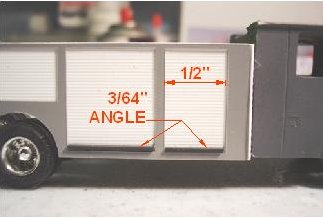
keen eye. In part 3, I mentioned trimming out the roll-up doors. Luckily I follow the old Carpenter’s adage of “measure twice, cut once.” I was ready to start laying in the door tracks on the Smeal, but a close look at the roll-ups on this particular truck revealed that there is very little trim work required. I would have ruined the work I have done so far since there are no tracks visible on the outside of the real truck, only the door grabs and knuckle guards** at the bottom. This makes life a tiny bit easier for me, but, I did say I would show you how to trim out the doors, as they look on most roll-up types. Once again, Plastruct products were used. The products used were: 3/64” 90-degree angle, 1/32” square rod, and 1/32” round rod. First, the width of the finished door opening is carefully measured, using a Vernier caliper. If you plan on getting into this hobby to the point where you will be doing a lot of precise cutting, I highly recommend that you buy an inexpensive Vernier caliper, similar to this one. I got one from Home Depot, and it cost me about $18.
The width dimension of the door, in this case ½” (or .5) is transferred to a piece of 3/64” angle which will serve as the knuckle guard, and the length is chopped with a new and sharp X-Acto blade. The ends of the angle are given a quick pass with an emery board to square them and remove any rough tailings. The piece of angle is then dropped into the door opening and “snugged” in by nudging it with the blade or a pair of angled tweezers, another highly recommended tool.
Now for the cement. For
very fine detail like this, I use a liquid adhesive called “Plasti-solve”,
also from Plastruct. This stuff is water-thin and evaporates
rapidly, and if used properly it won’t mar the surface of your
model. Because it’s water thin, you exploit its capillary properties
to make your joint. Simply daub a tiny amount at the joint, and it
will be drawn underneath the angle. Press down lightly on the angle
to form the bond. Another advantage of this product
is that you will have a few seconds to reposition your part or
remove it without causing damage. If you use superglue for this type
of work, you only get one chance and no time at all. The main
drawback is that this stuff has dangerous vapors, and must be used
sparingly and with adequate ventilation. I have had a few pounding
headaches from it.
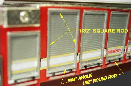
The door tracks are visible on
the outside surface. These were made from 1/32” square rod. The
lengths were cut to suit the door opening, as shown above. The
vertical pieces are slightly shorter than the actual height to
accommodate the knuckle guard angle at the base of the door. On any
type of roll-up door, there is a handle. This is made from 1/32”
round rod, cut to the width of the door + tracks, and tucked into
the knuckle guard. The black hinges are made from hair-thin styrene
rod wrapped around the handle, then highlighted with black paint.
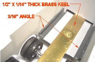
I attached 3/16”angle to the sides of the baseplate, lined up precisely with the edge. This gave me a vertical surface to attach the body panels that I made earlier. A piece of diamond plate finishes out the front of the body
I will use more 3/16 angle on the
top edges of the body panels when I’m ready to attach the deck.
Before I do that, I have to assemble and install the outrigger
system. I will cover that in the next segment. I welcome and
encourage your comments, questions, and suggestions, so consider
this project as something like an open book. Until then, thanks
again fro reading, and stay safe! |